Print frame / layout
Stamps are title blocks that contain planning information. The layout area of visual-STORE allows inserting stamps and assigning texts to the stamp via attributes.
Create stamps
- Draw stamps directly in a plan: use the drawing elements (Start tab) in pCon.planner to create the frame geometry.
- Integrate a logo if necessary.
- Insert attributes to specify the texts for the stamp.
- Create a group from the stamp (Select all and group > CTRL + G).
- Save the stamp as a DWG.
- To use the stamp for future planning, use the Stamp option in the
Insert group of the layout area.
Tips for drawing stamps:
- To display the stamp correctly on layout pages, set the insertion unit of the planning in which you are drawing the stamp to millimetres (File > Document properties > Tab > Settings > Select insertion unit of drawing > Millimetres).
- Make sure that the width of the stamp matches the print format. Example: A4 portrait format is 210 mm wide.
- If necessary, subtract a margin to obtain the width of the stamp - e.g. 200 mm.
- Stamp with colored background: Use a filled drawing element as background. Set this to height 0 of the user coordinate system.
- For correct display in the layout, position all other elements of the stamp, such as text, logos, attributes, etc., approx. 0.1 mm higher. The distance between the colored background and stamp elements should not exceed 1 mm.
Define attributes
Once the stamp has been drawn, fill it with attributes, which are assigned text values in the finished stamp. You create attributes in pCon.planner using the Create attributes button (Article, Attribute tab). Proceed as follows:
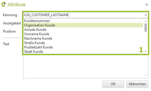
- Click the Create attributes button.
- The dialog Attributes opens. In the dialog, select a name for the attribute from the drop-down list under Name (1 in the first screen). These predefined identifiers represent characteristics from the document properties or the program settings, i.e. they are automatically assigned the values from the document properties or program settings when the stamp is inserted into a layout
- Alternatively, enter an individual name for the attribute. The identifier must be unique!
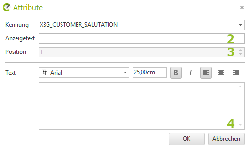
- Define a display text(2 in the second image). This determines the name of the attribute in the properties editor in the layout area.
- Specify a numerical value if you are using multiple attributes. The Position option(3) determines the order of the attributes in the properties editor.
- Use the Text field(4) to specify the text that is displayed as the default value in the stamp. Important: If you are using attributes from the drop-down list and defaults have been stored for these in the document properties or settings, the default value will be overwritten with these values when the stamp is inserted into a layout.
- Adjust font, font size, etc. for the attribute.
- Confirm your entries in the Attributes dialog with OK.
- Position the attribute with a mouse click at the desired position in the stamp.
- Save the stamp as a separate DWG file (Select stamp; File > Save selection)
- To use the stamp for future planning, use either the Imported option in the Layout area (for *.dwt files) or the Stamp option in the Insert group of the Layout area (to open a dwg file)