Generate image with OSPRay
To render the planning you have created, please go to "Presentation" in the upper tab. There click on the icon for image.
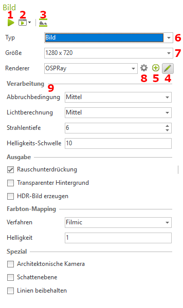
In this area you can make all settings that are important for the rendering, such as: the render quality.
The render window:
- Starts the rendering
- Starts batch rendering
- Displays the area that will be rendered
- Edit render profile
- Create new render profile
- Setting the type
- Image
- Panorama
- Multi Content Picture
- Setting the image size
- Renderer selection
- Edit the basic settings
Options:
1. termination condition:
- Here you can set the image quality at which the rendering process should end. For Preview, Medium or High, the calculation stops automatically as soon as the specified quality level is reached. If you set the level to unlimited, the image calculation will continue until you click Stop in the image dialog.
- Use the Custom option to define your own variance threshold as a termination criterion.
2nd variance threshold:
- Available for termination condition User-defined. Statistical value as a measure of the remaining noise. The smaller the value (tends towards 0), the more correct the image. We recommend a value of 1.5.
3. light calculation:
- Specifies the accuracy of the light calculation. The default value is Medium
4. beam depth:
- Beam depth for path tracing. Specifies how often a light beam is reflected in the scene. It is recommended to keep the preset value (6-8).
5. brightness threshold:
- A low value prevents aliasing effects in very strongly illuminated image areas. Low values also reduce the contrast in the image.
6. create HDR image:
- The rendering is output as an HDR image (High Dynamic Range Image).
7. color tone mapping:
- Selection of the method for adjusting the color gamut within an image to match the display capacity of conventional monitors, so that the rendered result appears as natural as possible to the viewer.
- Here you can choose between Simple, Filmic, Drago and Reinhard. Filmic is the default method. Filmic, Drago and Reinhard compress the contrast range in brighter areas of the image more than in darker areas. These methods produce more dynamic images compared to Simple.
- Simply filters out all color values from the image that are too bright to be displayed on a conventional monitor.
8 Architectural camera:
- If this box is deactivated, the standard camera is used. The image is calculated in a real perspective. If you check the box Architectural camera, the perspective display is rectified, which means that all vertical edges in the planning are also displayed vertically in the rendering.
9. shadow plane:
- If you activate this option, a transparent layer is inserted on the zero layer. This creates realistic shadows under individual 3D models.
Use this option to create photorealistic images of free-standing products. The background of the image contains the shadow cast by the depicted object. - It is recommended to set the background to Transparent. Then product images are created, which you can further edit including the shadows in image editing programs and place in other scenes
- We recommend setting the hue mapping to Simple.
- Also, make sure that the product models are level with the zero plane of the world coordinate system.
10. maintain lines:
- This setting means that not only spatial objects and surfaces are taken into account during the photorealistic calculation of an image, but also primitive lines and 2D characters. These are then visible in the calculated image.
- You can additionally enter a factor via Line width factor by which the line widths are multiplied and thus influence the width of the lines in the print result.